Coralba C Rally or GIANT Wiring
Posted by tcorey

tcorey Todd Corey Super Moderator Location: Western Australia Join Date: 09/22/2010 Age: Ancient Posts: 12 Rally Car: Audi |
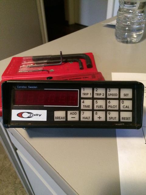
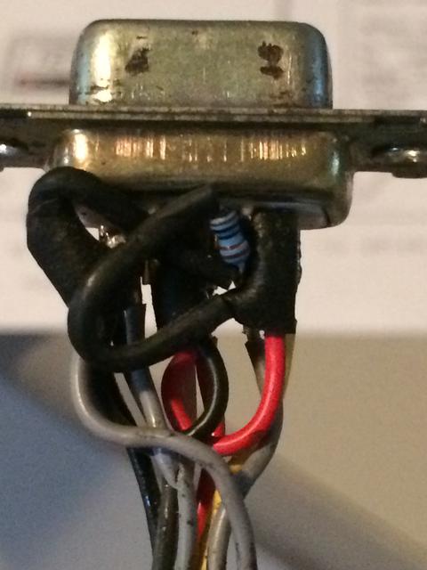
I recently purchased a used Coralba C Rally Trip Computer display unit and I separately acquired a wiring harness for the computer but found that the wire colour coding doesn't correspond to what's detailed in the Coralba installation manual and it has been modified. I'm asking for some technical help. If anyone has a Coralba C Rally or GIANT Trip Computer (harness is the same), can they disassemble the 9 pin connector. The connector is easy to disassemble and each pin is numbered on the connector and on the display unit. I need to know what function is performed by each of the 9 pins on the connector. Such as Pin 1 – 12 v to battery, Pin 2 to battery ground, Pin 3 to fuel transmitter etc. Be interested to know what the wire colours are for each Pin. I hope someone can provide this information.
|


Not Trolling Keith Morison Super Moderator Location: Calgary, AB Join Date: 09/15/2015 Age: Ancient Posts: 340 |
have you tried info@jemba.se
First Rally attended (2000), First Rally competed in (2001) Cars Built (1), Engines Built (0) Cages Built (0) Driver (8), Co-Driver (47), Drivers (19) Clerk (29), Steward (1), Official (17), Volunteer (5) WRC Spectator (1), WRC Photographer (6), WRC Observer (4) Rallies attended (120) Countries attended rallies in (11) Last Updated, May30, 2022 |
tcorey Todd Corey Super Moderator Location: Western Australia Join Date: 09/22/2010 Age: Ancient Posts: 12 Rally Car: Audi |
Yes, I have tried Jemba and they are not willing to provide me the information I need. Jemba must have purchased the design and distribution rites from Coralba. When you do Google searches there are others who have faced the same problem and I suspect are forced to purchase a replacement harness at a high cost for not much more than 5 wires and a common 9 pin connector. It's frustrating.
|
Not Trolling Keith Morison Super Moderator Location: Calgary, AB Join Date: 09/15/2015 Age: Ancient Posts: 340 |
1 - green
2 - white 3 - Red 4 - grey 5 - yellow 6 - pink 7 - brown 8 - Braid 9 - Blue I beleive some of these are unused in a normal application, they also go to a 'junction' under heatshrink that might hide some colour changing, if they want to be sneaky, but I don't have the time now to open that up. The cable aslo includes a din plug That goes to the speed sensor connections they have... which shows some of the same colours going there as leave for other uses. Maybe I can do a continuity check some day... but it won't be soon. First Rally attended (2000), First Rally competed in (2001) Cars Built (1), Engines Built (0) Cages Built (0) Driver (8), Co-Driver (47), Drivers (19) Clerk (29), Steward (1), Official (17), Volunteer (5) WRC Spectator (1), WRC Photographer (6), WRC Observer (4) Rallies attended (120) Countries attended rallies in (11) Last Updated, May30, 2022 |
tcorey Todd Corey Super Moderator Location: Western Australia Join Date: 09/22/2010 Age: Ancient Posts: 12 Rally Car: Audi |
Keith,
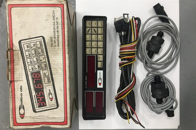
Thanks for that data. I'm prepared to wait if you have time to disassemble the connector and do a continuity check. Better to be patient than see this computer go up in smoke. I downloaded a photo of a new computer and harness. The harness has only 5 wires red, black, white, brown and yellow. The same colours as per the Coralba manual. Why different to yours? Todd |

Not Trolling Keith Morison Super Moderator Location: Calgary, AB Join Date: 09/15/2015 Age: Ancient Posts: 340 |
Sorry for the delay...
The factory cable goes to 5 wires that are exposed: Red (12v+) Brown (12v- ground) Yellow (reverse trigger or programable remote trigger) White (trip 1 reset) Black (fuel sender) And to a 5 pin DIN connector that plugs in to the various speed senders they have available. for the 9 pin serial - I get: 1 - Black (fuel sender) 2 - White (trip 1 reset) 3 - 4 - Red 12v+ 5 - Yellow (reverse/programable remote) 6 - Red 12v + 7 - 8 - Brown (ground) 9 - On the 5 plug DIN: 
1 connects to 7 4 connects to 6+4 (12v+) 2 connects to 9 5 doesn't connect 3 connects to 4 (but not 6, so might be 5v+?) That tells me 7 and/or 9 will be your signal wires for your speed sensor. That should be enough for you to power it up and see what voltages come back out... proceed with caution. Edited to add black wire connection that I originally missed. First Rally attended (2000), First Rally competed in (2001) Cars Built (1), Engines Built (0) Cages Built (0) Driver (8), Co-Driver (47), Drivers (19) Clerk (29), Steward (1), Official (17), Volunteer (5) WRC Spectator (1), WRC Photographer (6), WRC Observer (4) Rallies attended (120) Countries attended rallies in (11) Last Updated, May30, 2022 |
Not Trolling Keith Morison Super Moderator Location: Calgary, AB Join Date: 09/15/2015 Age: Ancient Posts: 340 |
I was giving the colours that are on the back of the 9 pin connector. But the wires go into a heat shrink bulge, and apparently get mixed up in there. First Rally attended (2000), First Rally competed in (2001) Cars Built (1), Engines Built (0) Cages Built (0) Driver (8), Co-Driver (47), Drivers (19) Clerk (29), Steward (1), Official (17), Volunteer (5) WRC Spectator (1), WRC Photographer (6), WRC Observer (4) Rallies attended (120) Countries attended rallies in (11) Last Updated, May30, 2022 |
tcorey Todd Corey Super Moderator Location: Western Australia Join Date: 09/22/2010 Age: Ancient Posts: 12 Rally Car: Audi |
Keith,
Managed to power up the display unit. I have a friend who is very good at electronics working with me, well I'm just watching for smoke. We are not sure why there is a 5V output on one of the pins. Hope to have it sorted or fried over the weekend. Fingers crosses all goes well. Your assistance and feedback has been invaluable. Todd |
Not Trolling Keith Morison Super Moderator Location: Calgary, AB Join Date: 09/15/2015 Age: Ancient Posts: 340 |
That should be the power supply to the speed sender. The ODOs I've used (TerrorTrip, Brantz Lazer, and Coralba) have all looked for a 5v pulse as the signal from the senders. First Rally attended (2000), First Rally competed in (2001) Cars Built (1), Engines Built (0) Cages Built (0) Driver (8), Co-Driver (47), Drivers (19) Clerk (29), Steward (1), Official (17), Volunteer (5) WRC Spectator (1), WRC Photographer (6), WRC Observer (4) Rallies attended (120) Countries attended rallies in (11) Last Updated, May30, 2022 |
Not Trolling Keith Morison Super Moderator Location: Calgary, AB Join Date: 09/15/2015 Age: Ancient Posts: 340 |
Can you tell me which pin gives 5v out? You have me curious now :-) First Rally attended (2000), First Rally competed in (2001) Cars Built (1), Engines Built (0) Cages Built (0) Driver (8), Co-Driver (47), Drivers (19) Clerk (29), Steward (1), Official (17), Volunteer (5) WRC Spectator (1), WRC Photographer (6), WRC Observer (4) Rallies attended (120) Countries attended rallies in (11) Last Updated, May30, 2022 |
tcorey Todd Corey Super Moderator Location: Western Australia Join Date: 09/22/2010 Age: Ancient Posts: 12 Rally Car: Audi |
On our connector PIN 4 is not used but has the 5V output. On the Evo 3 Lancer it is cable drive speedo. I'm using a Hunter H61 8 Pulse Transmitter connected to the gearbox speedo drive that has three wires, a positive wire, a negative wire and output from the transmitter.
So far we think - PIN 1 unidentified but think is to fuel transmitter PIN 2 think is output for reverse but has a 4V output. PIN 3 has two wires attached looped to PIN 6, one is 12V from battery. Other positive wire from Pulse Transmitter. PIN 4 not used but has 5V output PIN 5 has two wires and is looped to PIN 8. Been using this a negative wire battery and from Pulse Transmitter PIN 6 looped to PIN 3 and has inline resistor. Don't know what value it is or why used PIN 7 not used PIN 8 looped to PIN 5 so should be a negative to ground PIN 9 looped to resistor. Output from Pulse Transmitter to Coralba. When we rotate to pulse transmitter it counts up on TRIP. Doing more work on this over the weekend. Todd |
Not Trolling Keith Morison Super Moderator Location: Calgary, AB Join Date: 09/15/2015 Age: Ancient Posts: 340 |
When you're looking at this:
Pin 2 - should be Trip 1 reset. After booting the C-Rally, press the '1- Trip 1' buttion and that displays the Trip 1 register in the display. Use the sender to count up some distance, and then ground the wire coming from pin 2 - that should reset the odo to zero. Pin 3 - not sure what is going on here, other than feeding your sender with 12v+ Pin 4 - would be power source for some senders asking for 5v+ Pin 5 - is for the 'yellow' wire in the manual, or the reverse trigger/programable remote. The instructions say this needs to be grounded if not in use... I've never done that, but explains why this is looped to pin 8. Pin 9 - seems confirmed as your speedo signal, you don't say where the resistor connects to. It MIGHT be worth trying the sender on 5v power (without the resistor) and see if it works. Or, if it works, don't mess with it. :-) First Rally attended (2000), First Rally competed in (2001) Cars Built (1), Engines Built (0) Cages Built (0) Driver (8), Co-Driver (47), Drivers (19) Clerk (29), Steward (1), Official (17), Volunteer (5) WRC Spectator (1), WRC Photographer (6), WRC Observer (4) Rallies attended (120) Countries attended rallies in (11) Last Updated, May30, 2022 |
tcorey Todd Corey Super Moderator Location: Western Australia Join Date: 09/22/2010 Age: Ancient Posts: 12 Rally Car: Audi |
Keith,
Today wasn't a good day. Started off well and confirmed PIN 2 is the remote TRIP 1 reset. The only display we didn't have was fuel which must have been from PIN 1 to fuel transmitter as this was the only unidentified wire remaining. We connected it to the transmitter and tried a fuel calibration by moving the sliding float without voltage to that wire. After setting empty we tried 10 litres and got the Ad.-Err error indication indicating unchanged voltage from two calibration points. We gave it 5V and moved the transmitter float level slider and things went bad. No smoke but now we cannot change the selector key function. Defaults and remains on TRIP 1. Display unit powers up, resets to TRIP 1 and that's all. My friend had a good look at the circuit boards and couldn't see anything burnt. Diodes intact. We decided to not play around with the fuel function and disconnected the wire to the fuel transmitter. I had another display unit and nervously plugged that in. It booted up correctly and we can select the different function and operator keys. Looks as though we have fried the original display unit. We are satisfied that if we don't use the fuel function all will be ok. I look back and think we spent a lot of time trying to nut this harness out and maybe I should have spent 130 pounds, purchased a new harness and saved a display unit. But if others are in a similar situation at least this thread will give them some guidance. I feel a bit gutted and thank you for your help. Time to drown my sorrows in a glass or ten of vino. Todd Edited 1 time(s). Last edit at 08/06/2017 06:46AM by tcorey. |
Not Trolling Keith Morison Super Moderator Location: Calgary, AB Join Date: 09/15/2015 Age: Ancient Posts: 340 |
Sorry to hear that.
My initial advice was going to be that you just suck it up and buy a harness. I chose not to because I could already imaging the berating and incessant name calling that would ensue from one of our forum elders. First Rally attended (2000), First Rally competed in (2001) Cars Built (1), Engines Built (0) Cages Built (0) Driver (8), Co-Driver (47), Drivers (19) Clerk (29), Steward (1), Official (17), Volunteer (5) WRC Spectator (1), WRC Photographer (6), WRC Observer (4) Rallies attended (120) Countries attended rallies in (11) Last Updated, May30, 2022 |
tcorey Todd Corey Super Moderator Location: Western Australia Join Date: 09/22/2010 Age: Ancient Posts: 12 Rally Car: Audi |
|
Sorry, only registered users may post in this forum.
Rally Anarchy © 2014 Corvus Digital –
Part of the AutoShrine Network –
Problems? Send an email to the Webmaster